Layers of the TCP/IP Model
Network Interface
Layer
Internet
Transport
Application
The figure below shows the four layers of the TCP/IP reference model.
The TCP/IP Reference Model
Application Layer |
Transport Layer |
Internet Layer |
Network Interface Layer |
Network
Interface Layer
This is the lowest in the TCP/IP protocol stack. The network interface layer
consists of device drivers and network hardware. This layer does not have any
standard set of protocols.
The functions performed by this layer are as follows:
Interfacing
with the network layer
Interfacing with device drivers and hardware
Interfacing
with the Internet Layer
The Internet layer adds its heads to the Internet layer data to frame the data.
Similarly, when data is received from the physical medium, the network interface
layer removes the network interface layer headers and passes the data to the
Internet layer.
Interfacing
with Devices and Hardware
Different types of hardware exist for the various types of networks. For example,
a NIC designed for a Token Ring network is different from that designed for
an Ethernet network. The Internet layer need not change for various types of
hardware. Different device drivers are written for different NICs. A device
driver is a software program that interfaces with the hardware and acts as a
bridge between the application software and hardware. The network interface
layer takes data from the Internet layer, and, based on the device driver in
use, passes it on to the appropriate NIC.
Internet
Layer
The Internet layer defines a protocol named IP, and it defines the format of
the IP Packet.
The functions performed by this layer are:
Routing
Fragmentation and reassembly
Routing
Routing is the process of moving data on a network so that it ultimately reaches
its destination. Routing consists of two activities, determining a path to the
destination and actually transferring the data.
32-bit numbers, called IP addresses,
identify the destination of a transmission. IP addresses are written as four
decimal-separated number between 0 and 255. For example, 192.16.232.1 is an
IP address. Based on the IP address, the router determines the network to which
it must forward the data.
Fragmentation
and reassembly
Every network has an upper limit ti the size of the packet that can be sent.
This limit is known as the maximum transfer unit (MTU). If the size of the data
to be sent is greater than the MTU, the network layer breaks the data into smaller
packets. This process is known as fragmentation. Additional information, such
as the sequence number of the computer receives the fragments, it reassembles
them before passing them on to the transport layer.
Different networks may have different MTU sizes. Therefore, the process of fragmentation and reassembly is an important responsibility of the network layer.
Transport
Layer
The transport layer is a true end-to-end layer. The Internet and network interface
layers pass data to the next hop in the network. The transport layer, however,
is unaware of intermediate hops. The transport layer on the sender’s computer
virtually communicates with the transport layer on the recipient’s computer.
In this way, the transport layer establishes a reliable communication between
the sender and the receiver. This layer defines two main protocols called TCP
and UDP. The functions of the transport layer are:
Providing connection-oriented reliable service
Providing connectionless unreliable service
Providing flow control
Providing error control
Application
Layer
End-user applications occupy this layer. At the Application layer, users interact
with the network. Some of its most common applications are e-mail, FTP, Telnet,
and Web browser.
Applications in this layer interact with the transport layer to request connections. After connections are established, the application exchanges data with other applications using TCP as the transport mechanism. When the data exchange is complete, the application indicates to the transport layer to break the connection.
The OSI (Open Systems Interconnection) model is the foundation for all communications that take place between computers and other networking devices. The International Organization for Standardization (ISO) began developing the OSI model in 1974, after the United States Department of Defense (DoD) developed and began using the TCP/IP (Transmission Control Protocol/Internet Protocol) stack. TCP/IP is a suite of protocols that work together to provide communication between network devices. It is important to note that the OSI model is just that: a model. It is not a protocol that can be installed or run on any system. TCP/IP, on the other hand, is a functioning protocol that enables computers to communicate. After many years of discussion, the OSI model was finally adopted in 1977. Today, it is used as the theoretical model for the way communication between devices, such as computers, takes place.
OSI (Open Systems Interconnection) model The communications model developed and adopted by the ISO in 1977. It defines how hardware and software should be developed to support specific functions for communication between devices.
International Organization for Standardization (ISO) An international standards organization dedicated to defining global communication and standards.
Devices Hardware that is capable of attaching
to a network and communicating with other hardware. Examples are computers,
printers, routers, repeaters, hubs, and bridges.
The OSI model is important to understand because it is the basis for all network
communication models that have been developed and implemented. Although it is
a theoretical model, it has defined the way in which devices interact since
the late 70s. Understanding the purpose of each layer and its relationship to
the other layers will help you design, implement, and, most importantly, troubleshoot
any network.
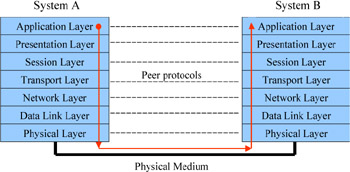
There are seven layers in the OSI model: Application, Presentation, Session, Transport, Network, Data Link, and Physical. These layers make up a framework that defines the way in hich physical hardware, media (such as cables), and software work together to communicate.
Each layer of the OSI model is independent from every other in its purpose and responsibilities. Each must do its own job, as well as provide the ability for information to move layers above and below it. In this way, the model creates a modular framework for understanding how network communication is taking place, as well as aid in troubleshooting problems that arise within a network.
As you can see in the following illustration, when two devices communicate, each device is responsible for utilizing each of the functions of each layer to ensure that the data will be transferred to the appropriate layer on the receiving end. For instance, the Application layer of node A communicates with the Application layer of node B by passing the data through the other layers. The Application layer of either node is not concerned with the functions of the other layers; as long as the other layers are doing their jobs, the Application layer can send and receive data and determine whether it has an application that can process the data. For example, if you send an HTTP request for a web page from a server that is not running web server software, the Application layer of the server will not be able to respond to the request. The result is that you see an error message on your screen.
How
Data Flows through the OSI Model
The movement of data through the OSI model is easy to follow. When two devices
want to communicate with each other, data will be sent from the Application
layer of the sending computer or device, referred to as the source.
The data, in the form of a packet, will continue
down the layers of the OSI model of the source device until it reaches the Physical
layer: layer 1. The Physical layer is where the data begins its journey out
into the network. source The
device in which data being sent over a network originates. data
A term used to represent the information that is transferred and formatted in
the top three layers of the OSI model.
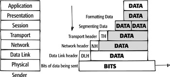
packet Describes the form of data after it has passed through the Transport layer. A packet is a group of bits that includes a header, data, and trailer; and can be transmitted over a network. At the Physical layer, the data represented in the computer as bits, or 1s and 0s, is converted into a format for transmission over the network. The information can be transmitted in the form of electricity, light, or radio waves. When the data reaches the destination device (the device that the source wants to talk to), it travels up the layers of the OSI model until it reaches the user.
destination A device on a network that is the recipient of data transmitted by the sender. As data flows down the OSI layers of the source computer, it is encapsulated with more and more information. The encapsulation process is illustrated as follows. Notice that as the data moves through the OSI layers, header and trailer information are added to the packet. The data inside the packet does not change. At the destination device, a similar process occurs. The information is decapsulated and sent up the OSI layers. It is each layer’s job to package—or unwrap—the data correctly for its neighbor.
encapsulated The process of enclosing
a packet of data with information from the current layer as it passes down the
OSI layers.
Decapsulated Layer information
is stripped from a packet as it moves up the OSI layers.
Understanding
Each OSI Layer
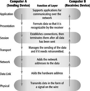
Part of each layer’s job is to perform specific functions for processing
the data before it is passed on to the layer above or below. For the sending
device, that means that each layer must process the data and prepare it for
the layer below it. For example, when the Session layer wants to begin a communication
session, it prepares to pass the data and instructs the Transport layer to create
the session.
In the receiving device, each layer provides
services to the layer below it. These services can be divided into horizontal
and vertical communications models. The communication between layers in the
same device is an example of the vertical communication model, also called “peer-layer
communication.” Network administrators, engineers, and software developers
have a better understanding of the OSI model when analyzing the communication
process horizontally.
At the top of the OSI model is the Application layer—the layer that is
the starting and ending point for a communication from a sending device to a
receiving device—which is referred to as layer 7. The “bottom”
layer, the one that actually sends the message on its way, is layer 1: the Physical
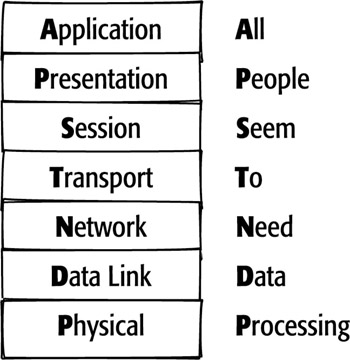
layer. This is often confusing for people. To remember the order of the layers,
try using a mnemonic device that begins with layer 1, the Physical layer, and
ends with layer 7, the Application layer. One common mnemonic device
is “All People Seem To Need Data Processing.”
mnemonic device A way
of remembering information by using a phrase, song, or some other method.
Layer 7: The Application Layer
The first layer of the OSI model we’ll look at is the layer closest to
the user, the Application layer. As noted earlier in this chapter, this is layer
7 of the OSI reference model. If you have viewed web pages from a web server,
then the data was processed by a protocol that functions at the Application
layer.
Application layer The
top layer of the OSI model. The Application layer formats data for a particular
function such as network printing, electronic mail, or web viewing.
Protocols functioning at the Application layer work with the applications you
use to communicate over the network. Examples of protocols that are needed for
applications to work on a network are SMTP (Simple Mail Transfer Protocol)
to send e-mail to a friend, HTTP (HyperText Transfer Protocol)
to access web pages while you are surfing on the Internet, or FTP (File
Transfer Protocol) to download a file from an FTP server.
Simple Mail Transfer Protocol (SMTP)
A protocol that specifies how electronic mail is to be delivered to its destination.
HyperText Transfer Protocol (HTTP) A protocol that defines how web pages are
processed by web servers.
File Transfer Protocol (FTP)
A protocol that defines how files are transferred to and from an FTP server
and a client computer.
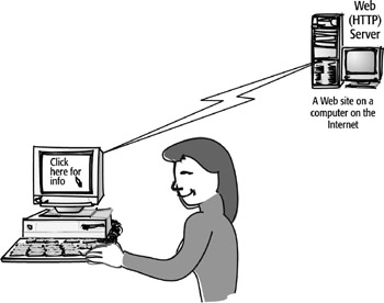
When you use your mouse to click on a link on a website or type in a URL on
the Internet, you are giving a command. This action tells the browser to retrieve
information from the appropriate web server on the Internet. When you request
information like a web page from the Internet, your computer is considered the
source and the website’s computer is the destination. The Application
layer’s services are used to complete the job and deliver the information
you requested.
The following illustration demonstrates
how this process works:
Application
Layer Services
There are literally hundreds of services that function at the Application layer.
It is a common mistake to equate the purpose of the Application layer with computer
applications or programs. Business productivity software, for example, does
not inherently run at the Application layer, although the software may make
use of network services.
There are five categories of services that are very common to most Internet
and network users. These categories are as follows:
File services The most
common of the services provided by the Application layer are file services.
File services may include requesting a web file to view a web page, as in the
previous example, or accessing a shared file on a local network.
File Services Any application that provides network users to files and folders
on a computer or server.
Note Remember that
a file does not have to be a text document. File types can include graphic files
such as JPEG, GIF, or PICT files; and videos in QuickTime or MP3 format. These
and other files, regardless of file format, are transmitted using some type
of file service that operates at the Application layer.
Electronic-mail services E-mail
servers rely on the SMTP protocol to pass e-mail messages to each other. SMTP
is the protocol that allows applications such as Sendmail in UNIX, Exchange
in Windows, and other e-mail server software to transfer messages to one another.
Network-printing services Unlike
printers that are directly attached to the computer, networked printers are
used in situations in which it is not economical to give each user a dedicated
printer. Networked printers are created by using either hardware- or software-based
print servers. The printer servers use various protocols to deliver print capabilities
to the clients over the network.
Application services
Networked applications were common in the first decades of networking. Computer
users relied on servers to give them access to applications. Due to the high
cost of hard drives, applications running on the user’s computer weren’t
even a consideration. Although personal computers are much more powerful today,
there are still many instances when a networked application makes more sense.
Database services One of the most common types of application services in use
is a database service. Databases are used in everything that requires the storage
and retrieval of information. On a network, database services use a number of
different upper-layer protocols to input and extract data in the database.
Layer 6: The Presentation Layer
Below the Application layer is the Presentation layer. This
is the sixth layer of the OSI model, one layer away from the end user. The Presentation
layer has three main jobs:
Data
presentation
Data compression
Data encryption
Presentation layer Layer 6 of the OSI model. The Presentation
layer manages the conversion from data structures used by the computer to a
form necessary for communication over the network.
The first function, data presentation, ensures that the data being sent to the recipient is in a format that the recipient can process. This function is important because it enables the receiving device to understand the information from the sending device. The sending device performs the data presentation service by turning the request from its own native format (its abstract syntax) into a common language (transfer syntax). For most computers, that common language is ASCII (American Standard Code for Information Interchange). ASCII uses 96 letters and numbers as well as 32 nonprinting characters.
abstract syntax The
format of data in the Application layer of the OSI model before it is converted
to any other format by the Presentation layer.
transfer syntax The format of data after it has been converted
by the Presentation layer into a “common language” format, typically
ASCII. If you were requesting services from an
IBM mainframe, the common language the Presentation layer would translate your
request into would be EBCDIC (Extended Binary Coded Decimal Interchange Code).
EBCDIC uses 256 special characters.
The second function of the Presentation layer,
data compression, shrinks large amounts of data into smaller pieces. This allows
data to be transferred more quickly across a network. data compression
The reformatting of data to make it smaller.
Note In networking, data is often referred to as a packet. Packet is the term used to identify data as it moves from device to device on a network.
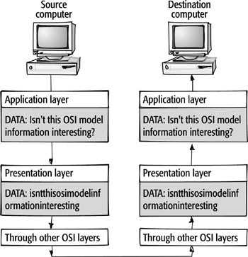
In the next example, the source computer has a simple text document to send
to the destination computer. At the Application layer, this data looks like
a normal sentence with formatting intact. Before the data can be sent to the
destination computer, the text passes through the OSI layers. When it reaches
the Presentation layer, the text data is compressed, transformed, and possibly
encrypted; then sent on through the remaining layers. At the destination computer,
when the information reaches the Presentation layer, it is returned to its original
format (with spaces and formatting), and then sent on to the Application layer.
The Presentation layer is also responsible for data encryption. Encryption is an important tool that allows us to hide information from everyone except the person who originally sent the information and the intended recipient.
encryption The process of converting data into a random set of characters that is unrecognizable to everyone except the intended recipient.
Note Not all messages sent across a network are or need to be encrypted Today, with the use of credit cards on the Internet, the prevalence of hackers, and the need for personal privacy, encryption of some sort has become almost a necessity.
When the encrypted message or data arrives at the destination device’s Presentation layer, the encryption service of the Presentation layer is responsible for decrypting the message. The destination device or its user must have the “key” to unlock the code. This is often in the form of a password that the user supplies, but may also include the use of a digital key that is created using software.
Layer
5: The Session Layer
Following down the model, the Session layer has the primary responsibility of
beginning, maintaining, and ending the communication between two devices, which
is called a session. It also provides for orderly communication between devices
by regulating the flow of data. The services that the Session layer is responsible
for include the following:
Establishing a connection
Maintaining the session
Ending the connection
Dialog control
Dialog separation
Session layer Layer
5 of the OSI model, the Session layer creates, maintains, and terminates communication
between devices on a network.
session A communication channel that is created and maintained
between two networked devices in order to transfer data.
Establishing, Maintaining, and Ending a Session
When a sending device first contacts a receiving device, it sends a syn (synchronization)
packet to establish communication and determine the order in which information
will be sent. The receiver sends back what is called an acknowledgment, or ack.
This is how the receiving computer acknowledges that there is a request to begin
a communication session. The session can then be set up. At the same time the
receiver sends the acknowledgment, it also sends a syn packet; this is necessary
for two-way communication to occur. At the end of the session, the sender transmits
an acknowledgment to request an end to the session. When the communication session
ends, protocols at the Session layer are responsible for its termination.
syn (synchronization) The message used to establish communication
between two or more systems.
ack (acknowledgment)
The message used to respond positively to a request for synchronization when
establishing a communication session between two devices.
The Session layer of the receiving device works with the Session layer of the
sending device to set up the rules of communication. The Session layers can
make decisions about the conversation based on the abilities of both devices,
limiting the number of packets sent and deciding who is going to transmit first.
Once a link is established, it must be maintained for as long as the communication
is taking place. One way the Session layer does this is through keep-alive messages.
These special messages maintain a connection between devices, even when there
is no data being transferred.
keep-alive message A data packet sent between Session layers to keep inactivity from causing the connection to close down.
After a communication has ended, it is
the responsibility of the Session layer to end the conversation. This guarantees
that the device with the open session is not sending erroneous data on the network
by continuing to send packets to the other device.
Dialog
Control
When a device is contacted, the Session layer is responsible for determining
which device participating in the communication will transmit at a given time,
as well as controlling the amount of data that can be sent in a transmission.
This is called dialog control. The types of dialog control that can take place
include simplex, half duplex, and full duplex.
dialog control A function of the Session layer that determines which device
will communicate first and the amount of data that will be sent.
Dialog
Separation
The Session layer is also responsible for inserting markers within messages.
The process of inserting markers, known as dialog separation, ensures that if
there is a loss of packets or any other problems during transmission, the conversation
can continue. The Session layer knows the data it needs to retransmit because
of the checkpoints it has placed within the message. dialog separation The use
of markers within the data to determine whether all information received is
intact.
Note In addition to dialog separation and dialog control, the Session layer is responsible for as many as 20 other services, most of which are used for exchanging information between systems.
Layer
4: The Transport Layer
The next layer of the OSI reference model is the Transport layer.
The primary function of the Transport layer is to ensure that the data packets
are sent and, depending on the network, that the data packets are received intact.
The Transport layer does this by using two types of transmission methods: connection-oriented
and connectionless.
Transport layer Layer 4 of the OSI model, the Transport layer takes the data from the Session layer and breaks it up into segments that can easily be transmitted by the lower-layer hardware. The Transport layer also has the job of managing the speed of communication between devices. This is known as flow control.
Connection-Oriented
Transmissions
Connection-oriented transmissions take place when the receiving device sends
an acknowledgment, or ack, back to the source after a packet or group of packets
is received. This type of transmission is known as a reliable transport method.
Because connection-oriented transmission requires that more packets be sent
across the network, it has often been considered a slower transmission method,
although today’s faster networks have made that argument a moot point.
connection-oriented
During communication between two devices, the receiving device will acknowledge
to the sender that it has received the data. If part of the data is not received,
the sender retransmits the data.
The features of connection-oriented transmission are the following:
Reliability
Slower communication
Packets are resent if a packet is unrecognizable or is not received
If there are problems with the data that is transmitted, the destination computer
requests that the source resend the data by acknowledging only the packets that
have been received and are recognizable. Once the destination computer receives
all of the data necessary to reassemble the packet, the Transport layer will
assemble the data in the correct sequence and then pass it up to the Session
layer for processing.
Connectionless Transmissions
Connectionless transmissions,
on the other hand, do not require the receiver to acknowledge receipt of a packet.
Instead, the sending device assumes that the packet arrived just fine. This
approach allows for much faster communications between devices. The trade-off
is that connectionless transmission is less reliable than connection-oriented
transmission.
connectionless When communication occurs between devices, there
is no acknowledgment that data has been received.
The features of connectionless transmission are as follows:
Little or no reliability
Faster transmission
Packets are not retransmitted
![]()
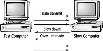
Flow Control
Another responsibility of the Transport layer is to make sure that the sender
and receiver communicate at a rate they both can handle. This is called flow
control. Flow control keeps the source from sending data packets faster than
the destination can handle.

flow control A Transport layer feature
that manages the flow of data. If the receiving device is unable to process
incoming data, it sends a message to halt the transmission; when able to continue,
it tells the sender to begin transmitting again. No matter which type of transmission
is used, the Transport layer will determine the largest size packet that can
be sent and proceed to divide the data in preparation for sending. The Transport
layer is also responsible for numbering these chunks so that the destination
computer can reassemble them in the right order.
Layer
3: The Network Layer
Below the Transport layer is the Network layer, layer 3. This layer is responsible
for the addressing and delivery of packets, also known as datagrams. The address
that the Network layer uses—the network address—is a logical address.
A logical address is still a number, but the number has no relationship to a
permanent physical address or to the hardware address on the network card.
Network layer Layer
3 of the OSI model, the Network layer takes the packets passed down from the
Transport layer, and adds the appropriate network addresses to them.
datagram A data packet that has had the network address added
to it as part of the encapsulation process.
network address The
address assigned by the network administrator, based on the network where the
device is located. Also known as the logical address.
To do its job, the Network layer must do the following:
Add the network address to the packet (through
encapsulation). With some network technologies, network addresses are assigned
by the system. In the case of the Internet, network addresses are assigned to
local devices by the network administrator; assigned dynamically by a special
server on the network; or, if a dial-up account to an Internet service provider
is being used, received from the ISP once the user logs on. The network addresses
available for use are received from InterNIC, RIPE (the European equivalent
of InterNIC), and APNIC (the Asia-Pacific equivalent of InterNIC).
InterNIC The organization responsible for managing the allocation of IP addresses and domain names for all organizations.
Map
the network address to the device’s physical address.
Determine the best path for the packet, based on information it has about the
network (this is called routing).
Ensure that the packet is in the correct format for the destination network.
How It Works
When a packet arrives at the Network layer, the Network layer adds source and
destination addresses through a process known as encapsulation.
Both addresses are logical. The first address that is added to the datagram
is the source address of the computer that is sending the data. Then the destination
address, again a logical network address, is added for the recipient computer.
The network addresses are necessary for packets to be transmitted between end
systems. These devices may exist on either a local network or on other
distant networks.
encapsulation In LAN protocols, the process of adding network
address information to a data packet. When the data packet has been encapsulated,
it is called a datagram.
end system A device
participating in a communication with another device.
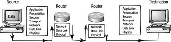
Before a packet can be sent to the destination device, the best path to that
device must be determined. For the Network layer to provide this service, called
routing, the source computer must address the packet using
the network address of the destination device. The network address allows the
Network layer to then make decisions about how to route the packet to the appropriate
network.
routing The use of a
routing protocol to select the best path to the appropriate network.
When the packet is sent, it may need to “switch” networks, again
using routing. The protocols operating at the Network layer provide routing
services by acting like an air traffic controller or traffic cop rerouting the
packet to the next segment of its journey.
Routing decisions are usually determined by calculating the shortest path needed to reach the destination, although other factors may apply. At the Network layer, routing decisions are made by routing protocols, which are implemented in software. In most cases, networks use dedicated devices called routers to perform this function.
The Network layer also has the job of making sure the data packet is in the correct format for the type of network it is entering. For example, if one network’s media allows for longer packet lengths, the Network layer will format the packets so that the network they are entering can handle them.
A router is the primary piece of hardware
that works at the Network layer. All the devices—such as routers—that
a packet passes through on its way to the destination device are called intermediate
systems. These intermediate systems need to deal with the packet only
up to the Network layer of the OSI model. They do not go any higher up the stack.
intermediate system Any device that is used to assist in transporting data between
two communicating end systems.
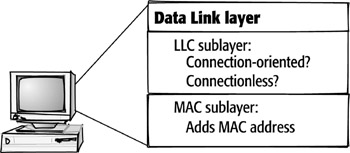
Layer 2: The Data Link Layer
The next layer of the OSI model is the Data Link layer. The
Data Link layer has two sublayers, and each provides its own services in the
OSI model. The first is the Logical Link Control (LLC) sublayer, and the second
is the Media Access Control (MAC) sublayer.
Data Link layer Layer 2 of the OSI model, the Data Link layer
receives data from the Network layer, and packages it as frames to be sent onto
the network by the Physical layer.
Logical Link Control (LLC) The LLC sublayer establishes whether communication
is going to be connectionless or connection-oriented at the Data Link layer.
Media Access Control (MAC) The MAC sublayer adds the destination and source physical addresses to a frame before sending it on to the Physical layer.
The LLC sublayer provides the interface between the media-access method and Network layer protocols such as the Internet Protocol, which is a part of the TCP/IP protocol suite. In contrast, the MAC sublayer is responsible for the connection to the physical media. Other Data Link layer functions include adding a device’s physical address (MAC address) to a datagram and converting the datagrams into frames to be transmitted over the network media.
media The means that
allow communication to take place—cable, for example.
The LLC sublayer uses two types of connection services that bridge the MAC sublayer
to the upper-layer protocols: connectionless and connection-oriented. As in
the Transport layer, a connectionless service assumes that data has arrived
correctly at the destination. The connectionless service, or LLC type 1, is
most common in today’s networks because the need for a connection-oriented
service is taken care of at the Transport layer.
Connection-oriented service, LLC type 2, checks that a message arrives correctly. Although it may seem that having this reliability is better, the extra work and time involved lowers the performance of the network, especially when this service is already provided at the Transport layer.
At the MAC sublayer of the Data Link
layer, the actual physical address of the device, called the MAC address,
is added to the packet as the encapsulation process continues. The packet, now
referred to as a frame, at last has all the addressing information necessary
to travel from the source device to the destination device. Without both the
physical MAC address given to it at this layer and the logical network address
given to it at the Network layer, a data packet will not arrive at its final
destination.
MAC address The address of the device that is found on the
NIC. Also known as the physical address.
![]()
A device’s MAC address is located on its network interface card (NIC).
The MAC address is permanently hard-coded on the card by the manufacturer. It
is a unique hexadecimal address that is not duplicated anywhere in the world.
It consists of six pairs of hexadecimal digits; the first six digits are assigned
to the NIC manufacturer and the last six are unique. This is truly the physical
address of the device.
network interface card (NIC) An electrical device installed
in a computer that allows it to be connected to a network.
hexadecimal A numerical system that uses the first six letters
of the alphabet to extend the possible digits to 16 beyond the 10 available
in the decimal system.
Tip Find out the
MAC address of your Windows 98 computer machine by typing winipcfg at the Run
or DOS prompt. It is listed as the hardware or adapter address. You can accomplish
the same task by using the ipconfig command at the same prompt in Windows NT/2000/Me/XP.
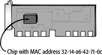
Note Cisco uses a dotted-hexadecimal notation format when identifying MAC addresses. It consists of three sets of two pairs each of hex digits. Thus, the previous MAC address would look like this: 3214.a642.710c.
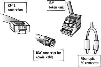
Layer 1: The Physical Layer
Below the Data Link layer is the Physical layer—the bottom layer or layer
1 of the OSI model. The Physical layer is responsible for the actual physical
connection between devices. This physical connection may be made using a variety
of materials such as the following:
Physical layer The bottom layer of the OSI model, the Physical layer specifies
the type of media to be used, the transmission format, and the topology of the
network.
Twisted-pair cable
Fiber-optic cable
Coaxial cable
Wireless communications
The same NIC that is involved in services
at the Data Link layer also helps at the Physical layer. The NIC is responsible
for converting the data, called bits, into transmission signals. The signals
generated by the NIC may be in a variety of formats, depending on the network
connection medium. These transmissions may be analog or digital,
though both types transmit binary data. The Physical layer
is also responsible for the rate at which these transmissions are sent.
analog A type of signal that uses a continuous waveform combining
amplitude, frequency, and phase.
digital A type of signal that uses pulses to send binary signals
across media. One pulse represents a 1; a lack of a pulse represents a 0.
binary A number system in which information is represented
as either a 1 or 0.
Another function of the Physical layer is that it manages the way a device connects
to the network media. For example, if the physical connection from the device
to the network uses coaxial cable, the hardware that functions at the Physical
layer will be designed for that specific type of network. All components, including
the connectors, will be specified at the Physical layer as well.
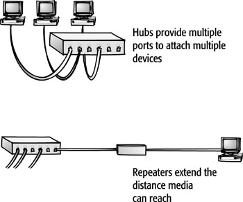
There are many devices that function specifically at the Physical layer. These include NICs, repeaters, hubs, and concentrators. These devices can regenerate the signals produced by the NIC as they travel through the network. If they will be moving onto a different type of network that requires a different type of signal or frame format, the devices can make changes to the format.
The Physical layer also determines the type of topology used by the network.